
API (American Petroleum Institute Standard) 5L is the international standard for steel pipe used in pipeline transportation systems.
API 5L covers steel pipe for a variety of applications for the transportation of natural gas, oil, and other liquids. Effective date of the 46th edition: effective November 1, 2018.
If you just want to get a general idea of API 5L, please click API 5L Pipe Specification Overview.
Navigation Buttons
What Has Been Updated in API 5L 46th
Origin of API 5L PSL
Classification of Steel Grades and Pipe Grades
Acceptable Delivery States
Raw Materials for Steel Pipes
Types of Steel Pipe and Tube Ends Covered by API 5L
Acceptable Manufacturing Processes for PSL2 Steel Tubing
Appearance inspection and common defects of API 5L
Dimensional Inspection (Dimensional Deviations)
API 5L Test Items
Pipe Marking and Location
Equivalence Standard
Our Related Products
What Has Been Updated in API 5L 46th
Updates
Updated and expanded requirements for milled joints;
Updated requirements for pipe end perpendicularity;
Updated hardness testing requirements for API 5LPSL 2 pipes for sour environments and API 5L PSL 2 pipes for offshore environments;
New
API 5L PSL 2 pipe for applications requiring longitudinal plastic strain capacity.
Origin of API 5L PSL
PSL: Pipeline Specification Level abbreviation ;
Divided into: API 5L PSL 1 and API 5L PSL 2.
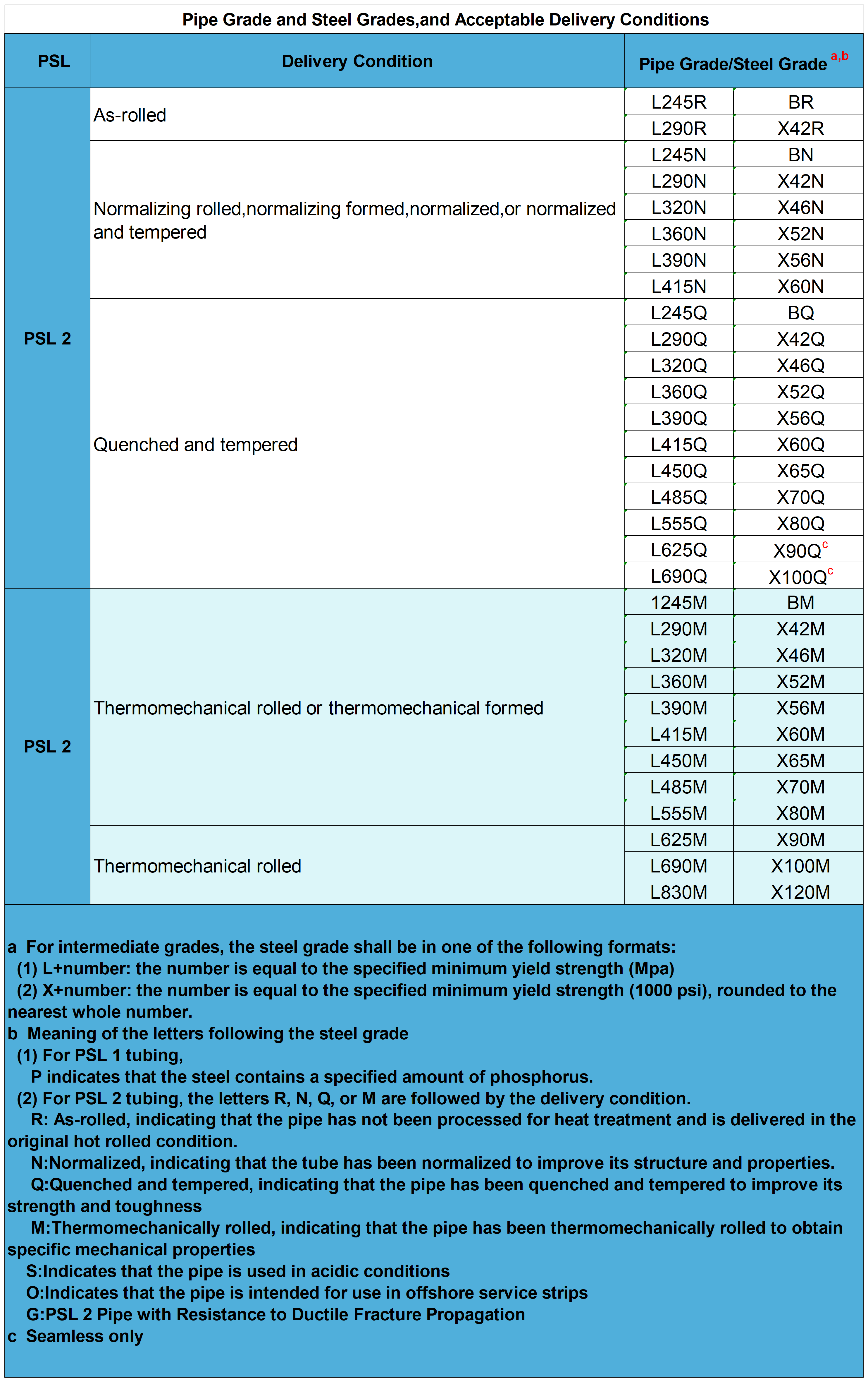
Classification of Steel Grades and Pipe Grades
L + number (the letter L is followed by the specified minimum yield strength in MPa):
L175、L175P、L210、L245、L290、L320、L360、L390、L415、L450、L485、L555、L625、L690、L830
X + number (the number following the letter X specifies the minimum yield strength in 1000 psi):
X42、X46、X52、X56、X60、X65、X70、X80、X90、X100、X120.
And grade a and grade b. Grade A=L210 Grade B=L 2459
Acceptable delivery states
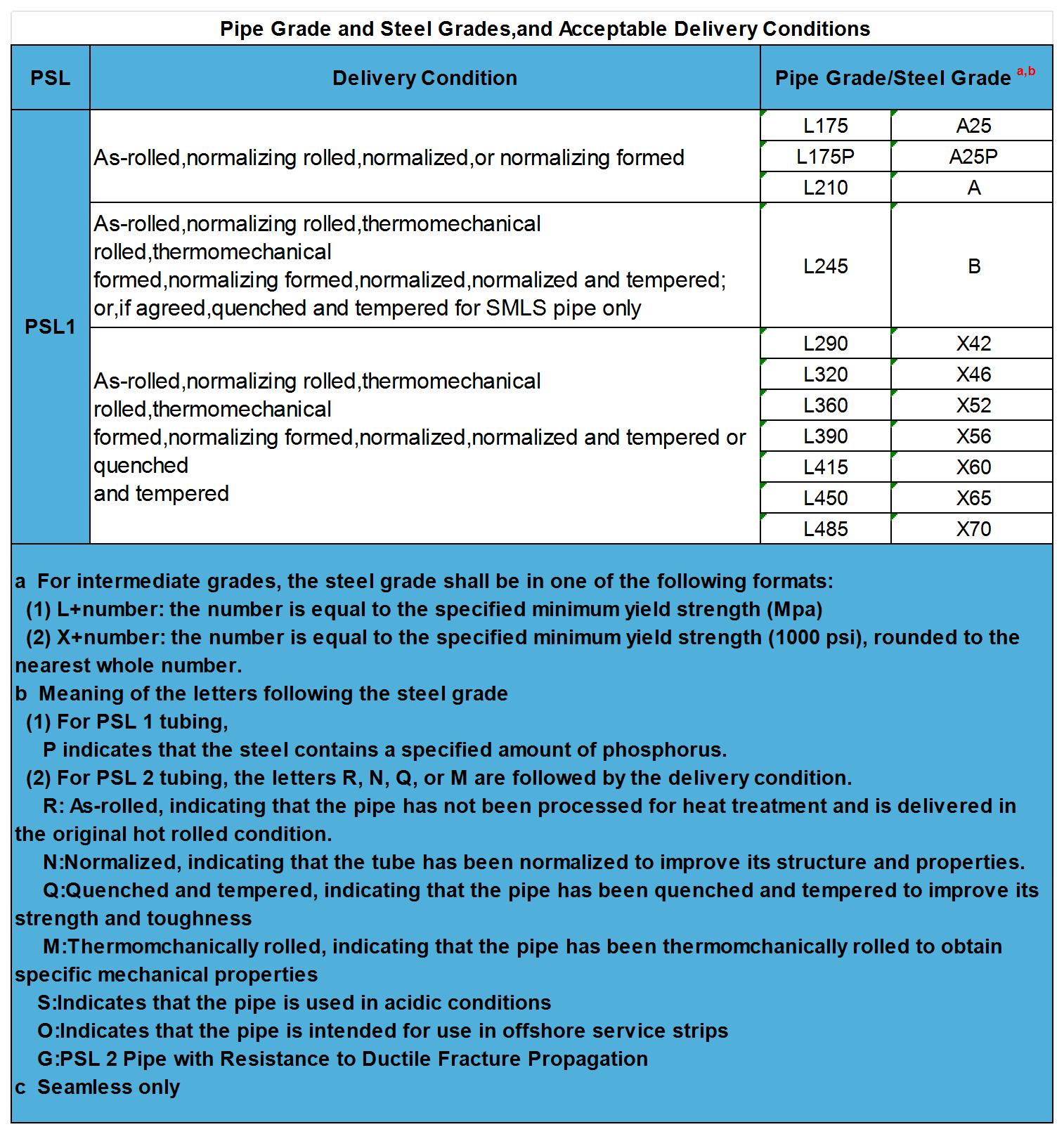
Note: L415/X60 or higher grades should not be used in place of L360/X52 or lower grades without the agreement of the purchaser.
Raw Materials for Steel Pipes
Ingot, billet, billet, strip (coil) or plate.
Note:
1. The raw material for API 5L PSL2 steel pipe shall be fine-grain sedimented steel.
2. Steel strip (coil) or plate used for the manufacture of API 5L PSL2 steel pipe shall not bear any tack welds.
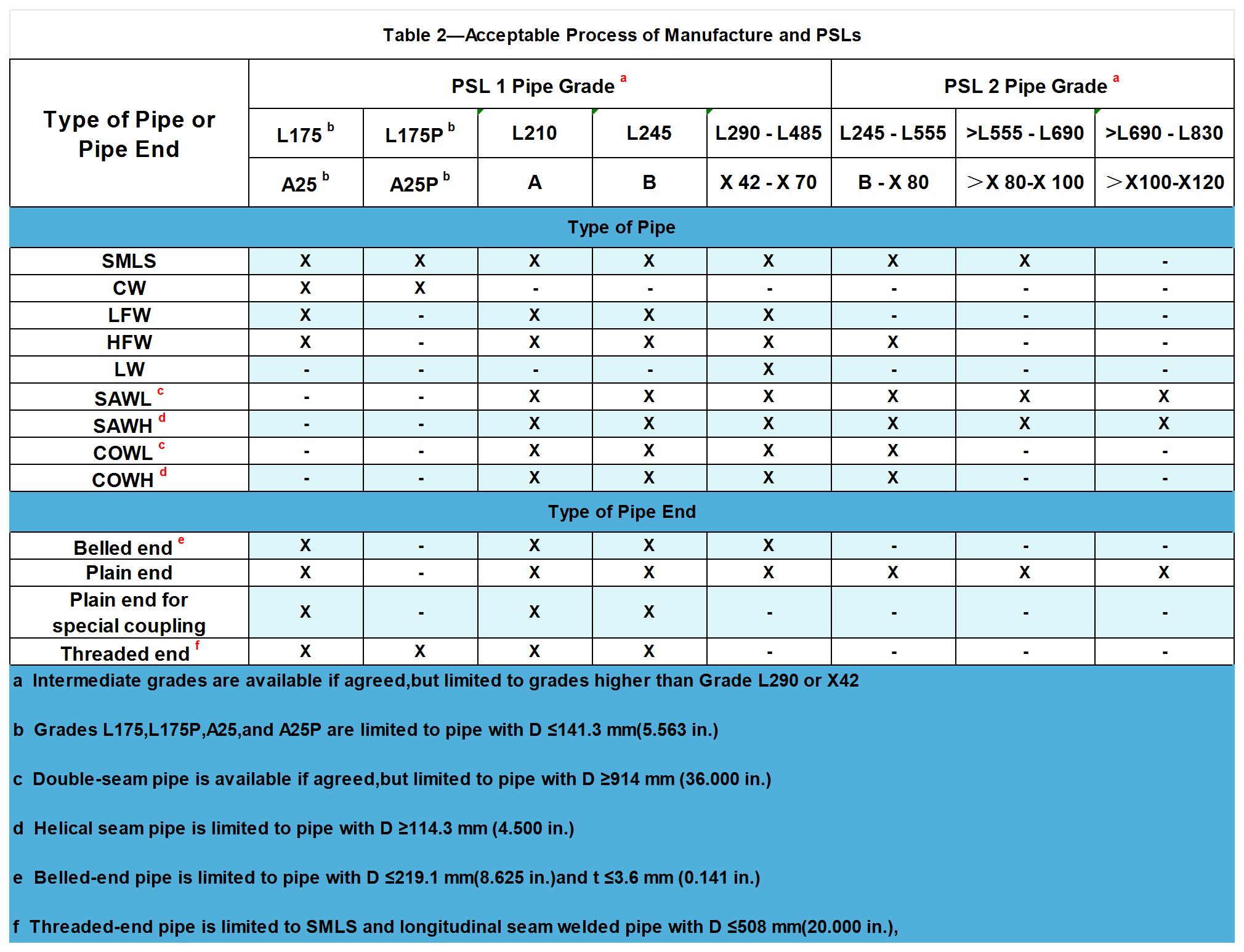
Types of Steel Pipe and Tube Ends Covered by API 5L
Welded Steel Pipe
CW Pipe: Process of forming a seam by heating the strip in a furnace and mechanically pressing the formed edgestogether, wherein successive coils of the strip had been joined together to provide a continuous flow of stripfor the welding mill.
COWH Pipe: Tubular product having one helical seam produced by a combination of gas metal arc and submerged arc welding, wherein the gas metal arc weld bead is not completely removed by the submerged arc welding passes.
COWL Pipe: Tubular product having one or two longitudinal seams produced by a combination of gas metal arc and submerged arc welding, wherein the gas metal arc weld bead is not completely removed by the submerged arc welding passes.
EW Pipe: Tubular product having one longitudinal seam produced by low-or high-frequency electric welding.
HFW Pipe: EWpipe produced' with a welding current frequency equal to or greater than 70 kHz.
LFW Pipe: EW pipe is produced with a welding current frequency of less than 70 kHz.
LW Pipe: Tubular product having one longitudinal seam produced by laser welding.
SAWH Pipe: Tubular product having one helical seam produced by the submerged arc welding process.
SAWL Pipe: Tubular product having one or two longitudinal seams produced by submerged arc welding.
Seamless Steel Pipe
SMLS pipe: Hot rolled seamless steel pipe and cold rolled seamless steel pipe, there are some other processing methods, such as cold drawing, cold drawing, forging, etc.
API 5L PSL2 Pipe types for special applications
Resistance to Ductile Fracture Propagation (G)
Sour Service Condition Pipe (S)
Offshore Service Condition Pipe (O)
Requiring Longitudinal Plastic Strain Capacity Pipe
Pipe End Types
Socket End, Flat End, Special Clamp Flat End, Threaded End.
Note:
1. Socket ends, pipe ends for special clamps, and threaded pipe ends are for API 5L PSL1 only.
2. L175 P/A25 P steel grade API 5L PSL1 steel pipe shall be machined with threaded ends, and API 5L PSL1 steel pipe of other steel grades shall be machined with flat ends.
3. API 5L PSL 2 tubes shall be delivered with flat ends.
Acceptable Manufacturing Processes for PSL2 Steel Tubing
| Table 3—Acceptable Manufacturing Routes for PSL 2 Pipe | ||||
| Type of Pipe | Starting Materia | Pipe Forming | Pipe Heat Treatment |
Delivery Condition |
| SMLS | Ingot, bloom,or billet | As-rolled | — | R |
| Normalizing forming | — | N | ||
| Hot forming | Normalizing | N | ||
| Quenching and tempering | Q | |||
| Hot forming and cold finishing |
Normalizing | N | ||
| Quenching and tempering | Q | |||
| HFW | Normalizing-rolled coil | Cold forming | Heat treating a of weld area only |
N |
| Thermomechanical-rolled coil |
Cold forming | Heat treating a of weld area only |
M | |
| Heat treating a of weld area and stress relieving of entire pipe |
M | |||
| As-rolled or thermomechanical-rolled coil |
Cold forming | Normalizing | N | |
| Quenching and tempering |
Q | |||
| Cold forming followed by hot reducing under controlled temperature resulting in a normalized condition |
— | N | ||
| Cold forming followed by thermomechanical forming of pipe |
— | M | ||
| SAW or COW |
Normalized or normalizing- rolled coil or plate |
Cold forming | — | N |
| As-rolled thermomechanical-rolled normalizing-rolled, or normalized |
Cold forming | Normalizing | N | |
| Thermomechanical-rolled coil or plate |
Cold forming | — | M | |
| Quenched and tempered plate |
Cold forming | — | Q | |
| As-rolled thermomechanical-rolled normalizing-rolled, or normalized coil or plate |
Cold forming | Quenching and tempering |
Q | |
| As-rolled thermomechanical-rolled normalizing-rolled,or normalized coil or plate |
Normalizing forming | — | N | |
| a See ISO 5L 8.8 for applicable heat treatments | ||||
Appearance inspection and common defects of API 5L
Appearances
The outer surface of the pipe shall be smooth and free from defects that may affect the strength and sealing properties of the pipe.
Major Defects
Nibbled edges: Nibbled edges can best be located by visual inspection.
Arc burns: Arc burns shall be judged as defective.
Arc burns are a number of localized spot defects formed by the melting of the metal surface caused by the arc between the electrode or grounding electrode and the surface of the steel pipe.
Contact spots are intermittent spots near the weld line of an EW pipe, caused by contact between the electrode supplying the welding current and the surface of the pipe.
Delamination: Any delamination or inclusion that extends over the surface of the pipe or beveled face and is >6.4 mm (0.250 in) in circumferential length on visual inspection shall be considered a defect.
Geometric deviations: A geometric deviation (e.g., a flat block or pout, etc.), other than a drop pit, caused by the tube forming process or manufacturing operation. The distance between the extreme point and the extension of the normal contour of the tube, i.e., a depth greater than 3.2 mm (0.125 in), shall be considered a defect.
Drop pits shall be ≤ 0.5 D in any direction.
Hardness: When visual inspection reveals suspected hardness, a portable hardness tester shall be used to conduct a hardness test, and a single-point indentation with a hardness value in excess of 35 HRC, 345 HV10, or 327 HBW shall be considered defective when the size of the indentation is greater than 50 mm (2.0 in) in any direction.
Defect Handling
Please refer to the relevant requirements in API 5L Appendix C for handling.
Dimensional Inspection (Dimensional Deviations)
Pipe Weight Chart and Weight Deviation
Weight Formula
M=(D-T)×T×C
M is the mass per unit length;
D is the specified outside diameter, expressed in millimeters (inches);
T is the specified wall thickness, expressed in millimeters (inches);
C is 0.02466 for calculations in SI units and 10.69 for calculations in USC units.
PIPE WEIGHT CHARTS AND SCHEDULES
pipe weight tables in API 5L are referenced to ISO 4200 and ASME B36.10M, which give standard values for pipe with specified outside diameter and specified wall thickness.
Schedule 40 and Schedule 80 are attached below, if you would like to see the full pipe schedule, please click here!
Weight Deviation
Quality of each pipe relative to the theoretical: weight: 95% ≤ theoretical weight ≤ 110;
Deviation and extra-thin specification tubes: 5% ≤ 110% of theoretical weight;
L175, L175P, A25, and A25P steel grades: 95% ≤ 110% of theoretical weight.
Outer Diameter and Wall Thickness Range
| Table 9—Permissible Specified Outside Diameter and Specified Wall Thickness | ||
| Specified Outside Diameter D mm (in.) |
Specified Wall Thickness t mm (in.) |
|
| Special Light Sizes a | Regular Sizes | |
| ≥10.3 (0.405)to<13.7 (0.540) | — | ≥1.7 (0.068)to≤2.4 (0.094) |
| ≥13.7 (0.540)to<17.1 (0.675) | — | ≥2.2 (0.088)to≤3.0 (0.118) |
| ≥17.1 (0.675)to<21.3 (0.840) | — | ≥2.3 (0.091)to≤3.2 (0.125 |
| ≥21.3 (0.840)to<26.7 (1.050) | — | ≥2.1 (0.083)to≤7.5(0.294) |
| ≥26.7(1.050)to<33.4(1.315) | — | ≥2.1 (0.083)to≤7.8 (0.308) |
| ≥33.4(1311}5)to<48.3 (1.900) | — | ≥2.1 (0.083)to≤10.0 (0.394) |
| ≥48.3 (1.900)to<60.3 (2.375) | — | ≥2.1 (0.083)to≤12.5 (0.492) |
| ≥60.3 (2.375)to<73.0 (2.875) | ≥2.1 (0.083)to≤3.6 (0.141) | >3.6 (0.141)to≤14.2 (0.559) |
| ≥73.0 (2.875)to<88.9(3.500) | ≥2.1 (0.083)to≤3.6 (0.141) | >3.6 (0.141)to≤20.0 (0.787) |
| ≥88.9 (3.500)to<101.6(4.000) | ≥2.1 (0.083)to≤4.0 (0.156) | >4.0 (0.156)to≤22.0 (0.866) |
| ≥101.6(4.000)to<168.3 (6.625) | ≥2.1 (0.083)to≤4.0 (0.156) | >4.0(0.156)to≤25.0 (0.984) |
| ≥168.3 (6.625)to<219.1 (8.625) | ≥2.1 (0.083)to≤4.0 (0.156 | >4.0 (0.156)to≤40.0(1.575) |
| ≥219.1 (8.625)to<273.1 (10.750) | ≥3.2 (0.125)to≤4.0 (0.156 | >4.0 (0.156)to≤40.0 (1.575 |
| ≥273.1 (10.750)to<323.9 (12.750) | ≥3.6 (0.141)to≤5.2 (0.203) | >5.2 (0.203)to≤45.0 (1.771) |
| ≥323.9(12.750)to<355.6(14.000) | ≥4.0 (0.156)to≤5.6 (0.219) | >5.6 (0.219)to≤45.0(1.771 |
| ≥355.6(14.000)to<457(18.000) | ≥4.5 (0.177)to≤7.1 (0.281) | >7.1 (0.281)to≤45.0(1.771 |
| ≥457 (18.000)to<559 (22.000) | ≥4.8 (0.188)to≤7.1 (0.281) | >7.1 (0.281)to≤45.0(1.771) |
| ≥559 (22.000)to<711(28.000) | ≥5.6 (0.219)to≤7.1 (0.281) | >7.1 (0.281)to≤45.0(1.771) |
| ≥711 (28.000)to<864(34.000) | ≥5.6(0.219)to≤7.1 (0.281) | >7.1 (0.281)to≤52.0 (2.050) |
| ≥864 (34.000)to<965(38.000) | — | ≥5.6 (0.219)to≤52.0 (2.050) |
| ≥965(38.000)to<1422 (56.000) | — | ≥6.4 (0.250)to≤52.0 (2.050) |
| ≥1422(56.000)to<1829 (72.000) | — | ≥9.5 (0.375)to≤52.0 (2.050 |
| ≥1829(72.000)to<2134(84.000) | — | ≥10.3 (0.406)to≤52.0 (2.050) |
| a Pipe having the combination of specified outside diameter and specified wall thickness is defined as a special light-size pipe; other combinations given in this table are defined as regular-size pipe. | ||
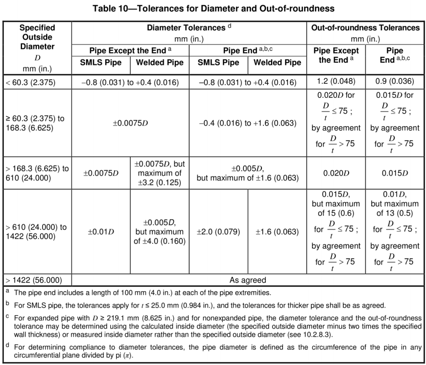
Diameter and Roundness Deviation
Wall Thickness Deviation
| Table 11—Tolerances for Wall Thickness | |
| Wall Thickness t mm (in.) |
Tolerances a mm (in.) |
| SMLS Pipe b | |
| ≤4.0 (0.157) | +0.6(0.024) -0.5 (0.020) |
| >4.0 (0.157)to<25.0 (0.984) | +0.150t -0.125t |
| ≥25.0 (0.984) | +3.7 (0.146)or+0.1t, whichever is the greater -3.0 (0.120)or-0.1t, whichever is the greater |
| Welded Pipe c d | |
| ≤5.0 (0.197) | ±0.5 (0.020) |
| >5.0 (0.197)to<15.0 (0.591) | ±0.1t |
| ≥15.0 (0.591) | ±1.5 (0.060) |
| a If the purchase order specifies a minus tolerance for wall thickness smaller than the applicable value given in this table, the plus tolerance for wall thickness shall be increased by an amount sufficient to maintain the applicable tolerance range.
b For pipe with D2 355.6 mm (14.000 in.) and 1 2 25.0 mm (0.984 in.), the wall thickness tolerance locally may exceed the plus tolerance for wall thickness by an additional 0.05t, provided that the plus tolerance for mass (see 9.14) is not exceeded. c The plus tolerance for wall thickness does not apply to the weld area. d See 9.13.2 for additional restrictions. |
|
Length Deviation
Fixed-length tubing tolerances: Length deviation should be 500 mm (20 inches).
Random length pipe tolerances:
| Table 12—Tolerances for Random Length Pipe | |||
| Random Length Designation m(ft) |
Minimum Length m (ft) |
Minimum Average Length For each Order Item m (ft) |
Maximum Length m (ft) |
| Threaded-and-coupled Pipe | |||
| 6(20) | 4.88(16.0) | 5.33 (17.5) | 6.86 (22.5) |
| 9(30) | 4.11 (13.5 | 8.00 (26.2) | 10.29 (33.8) |
| 12 (40) | 6.71 (22.0) | 10.67(35.0) | 13.72(45.0 |
| Plain-end Pipe | |||
| 6(20) | 2.74 (9.0) | 5.33 (17.5) | 6.86 (22.5) |
| 9 (30) | 4.11 (13.5 | 8.00(26.2) | 10.29 (33.8) |
| 12 (40) | 4.27 (14.0 | 10.67 (35.0) | 13.72(45.0) |
| 15(50) | 5.33 (17.5) | 13.35(43.8) | 16.76(55.0) |
| 18(60) | 6.40 (21.0 | 16.00 (52.5) | 19.81 (65.0) |
| 24(80) | 8.53 (28.0) | 21.34(70.0) | 25.91(85.0) |
Straightness Deviation
Total deviation from a straight line over the entire length of the pipe shall be <0.2% of the pipe length;
Localized deviation from a straight line shall be <3.2 mm (0.125 in) over a 1.5 m (5.0 ft) length of each pipe end.
Bevel Angle Deviation
Tube with t > 3.2 mm (0.125 in) flat ends shall be machined with a weld bevel with a bevel angle of 30°-35°.
Width of Develed Root Surface
1.6 mm (0.063 in) with a deviation of ±0.8 mm (0.031 in).
Range of Inner Cone Angle (only for seamless steel pipe)
| Table 13—Maximum Angle of Internal Taper for SMLS Pipe | |
| Specified Wall Thickness t mm (in.) |
Maximum Angle of Taper
degrees |
| <10.5(0.413) | 7.0 |
| 10.5 (0.413)to<14.0 (0.551) | 9.5 |
| 14.0 (0.551)to<17.0 (0.669) | 11.0 |
| ≥17.0 (0.669) | 14.0 |
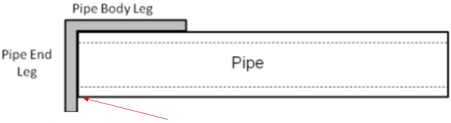
Pipe End Squareness (out-of-squareness)
The out-of-squareness is measured as the gap between the end of the pipe and the pipe end leg, which shall be 1.6 mm (0.063 in.).
Welding Seam Deviation
Strip/Sheet Misalignment:
For electro-welded (EW) and laser-welded (LW) pipe, the misalignment should not result in a remaining wall thickness at the weld that is less than the minimum allowable wall thickness.
For the Submerged Arc Welded (SAW) and Combination Welded (COW) pipe, the misalignment should not exceed the corresponding values given in Table 14 of API 5L.
Burrs ( electro-welded (EW) and laser-welded (LW) tubes) :
Outer burrs shall be removed to a substantially flush condition (with the base material).
Internal burrs shall not extend 1.5 mm (0.060 in) beyond the contour of the tube, and the wall thickness at the point of burr removal shall not be less than the minimum allowable wall thickness.
Weld Height ( Submerged Arc Welding (SAW) and Combination Welding (COW) Pipe):
Remove the remaining height of the internal weld within a minimum of 100 mm (4.0 in) of the pipe end at each end of the pipe, and grind the weld so that it does not rise more than 0.5 mm (0.020 in) above the surface of the adjacent pipe.
API 5L Test Items
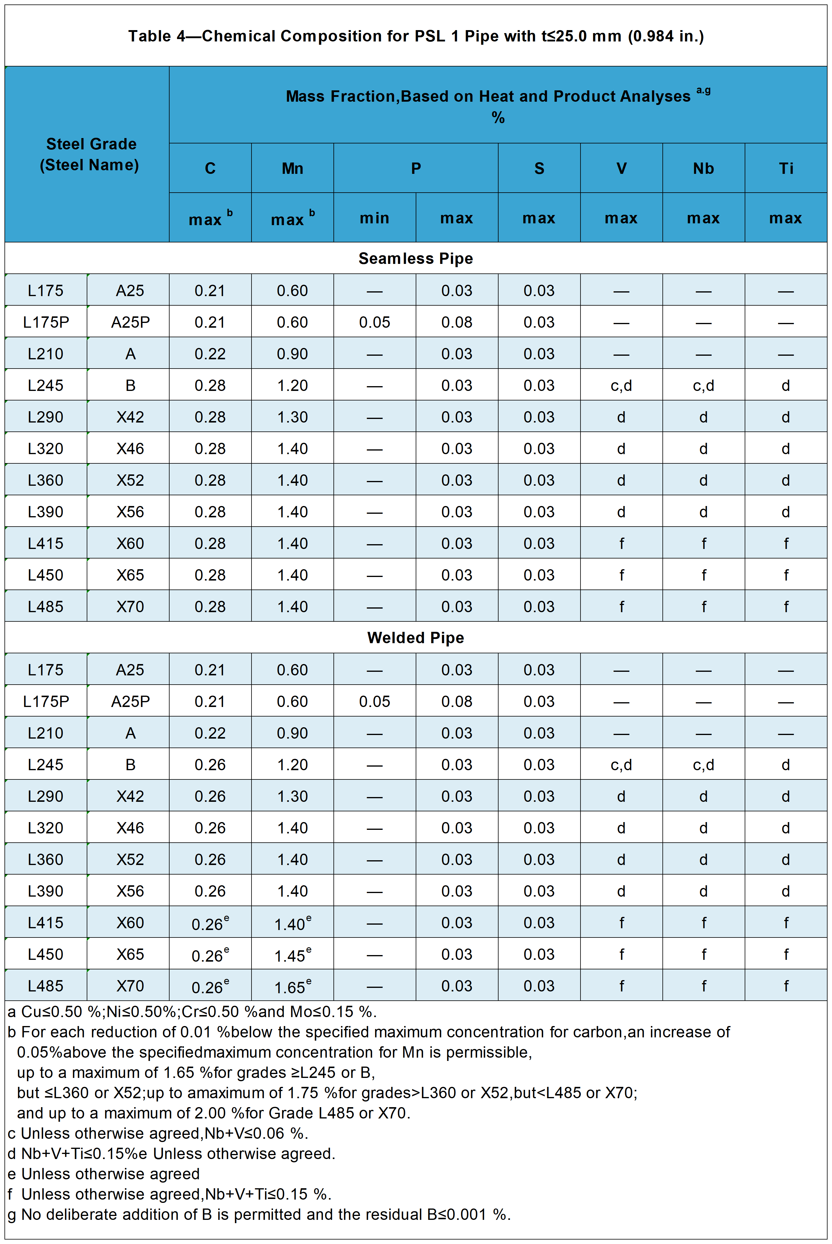
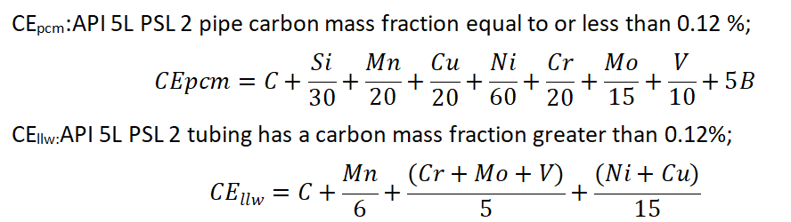
Chemical Composition
Test Method: Refer to ISO 9769 or ASTM A751.
The chemical composition of API 5L PSL1 and API 5L PSL2 steel pipe t > 25.0 mm (0.984 in) shall be determined by negotiation based on the chemical compositions in the corresponding tables.
Chemical Composition for PSL 1 Pipe with t≤25.0 mm (0.984 in.)
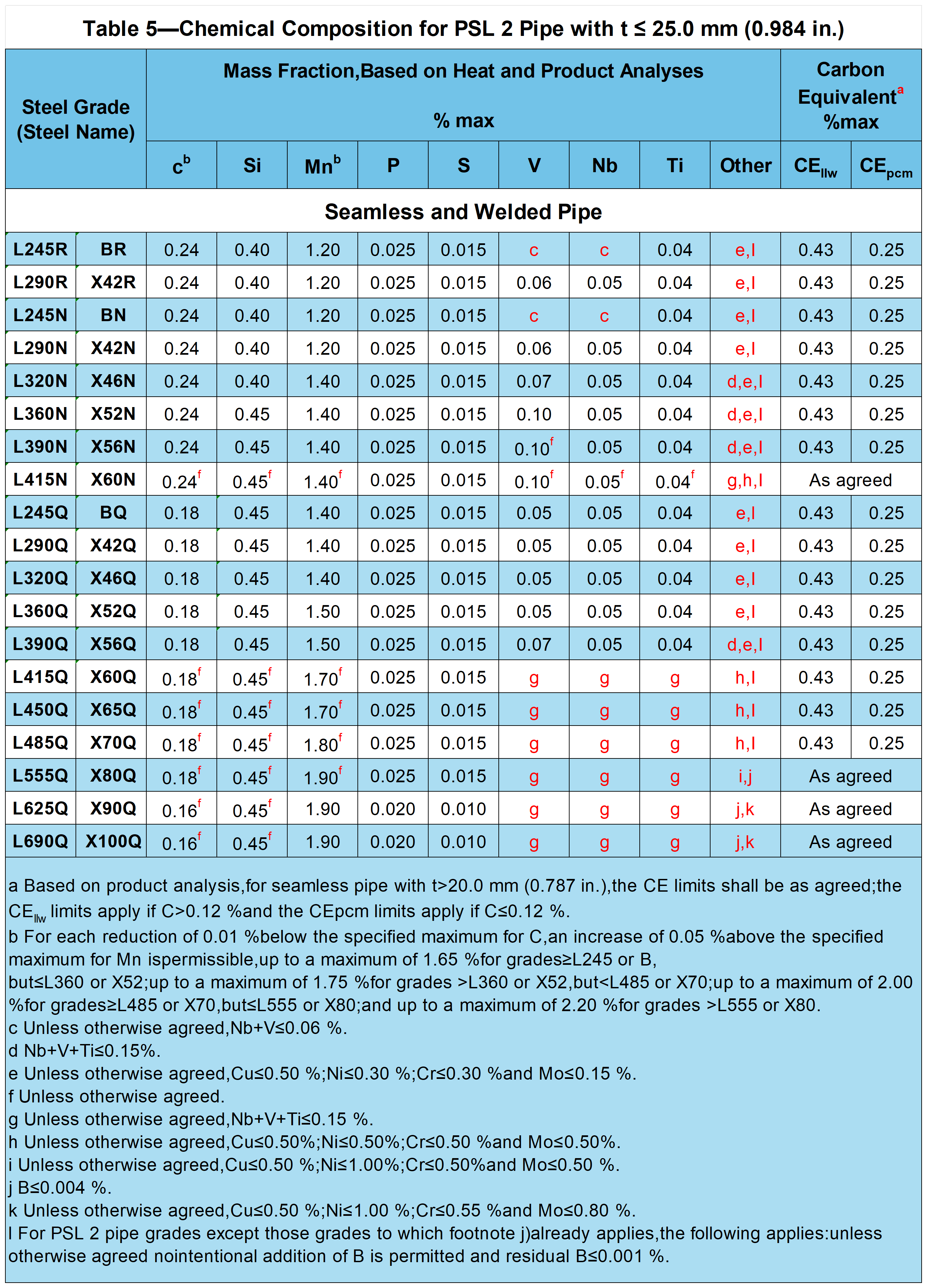
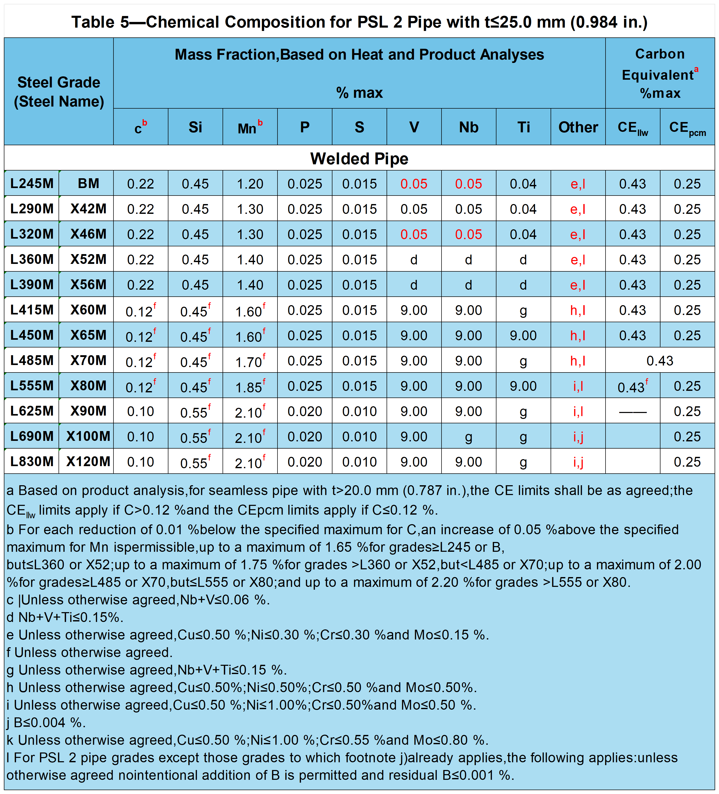
Chemical Composition for PSL 2 Pipe with t≤25.0 mm (0.984 in.)
Tensile Properties
Test Methods: Shall be performed in accordance with ISO 6892-1 or ASTM A370.
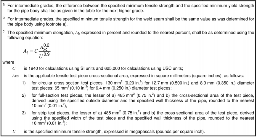
Requirements for the Results of Tensile Tests for PSL 1 Pipe
| Table 6—Requirements for the Results of Tensile Tests for PSL 1 Pipe | ||||
| Pipe Grade | Pipe Body of Seamless and Welded Pipe | Weld Seam of EW, LW, SAW, and COW Pipe |
||
| Yield Strength a Rto.5 MPa(psi) |
Tensile Strength a Rm MPa(psi) |
Elongation (on 50 mm or 2 in.) Af % |
Tensile Strength b Rm MPa(psi) |
|
| min | min | min | min | |
| L175 or A25 | 175(25,400) | 310(45,000) | c | 310(45,000) |
| L175P or A25P | 175(25,400) | 310(45,000) | c | 310 (45,000) |
| L210 or A | 210 (30,500) | 335(48,600) | c | 335(48,600) |
| L245 or B | 245 (35,500) | 415(60,200) | c | 415(60,200) |
| L290 or X42 | 290(42,100) | 415(60,200) | c | 415 (60,200) |
| L320 or X46 | 320 (46,400) | 435 (63,100) | c | 435 (63,100) |
| L360 or X52 | 360 (52,200) | 460(66,700) | c | 460 (66,700) |
| L390 or X56 | 390 (56,600) | 490(71,100) | c | 490(71,100) |
| L415 or X60 | 415 (60,200) | 520(75,400) | c | 520 (75,400) |
| L450 or X65 | 450(65,300) | 535(77,600) | c | 535(77,600) |
| L485 or X70 | 485(70,300) | 570 (82,700) | c | 570 (82,700) |
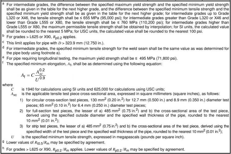
Requirements for the Results of Tensile Tests for PSL 2 Pipe
| Table 7—Requirements for the Results of Tensile Tests for PSL 2 Pipe | |||||||
| Pipe Grade | Pipe Body of Seamless and Welded Pipe | Weld Seam of HFW SAW and CoW Pipe |
|||||
| Yield Strength a Rto.5 MPa(psi) |
Tensile Strength a Rm MPa (psi) |
Ratio a.c
Rt0.5/Rm |
Elongation (on 50 mm or 2 in.) Af % |
Tensile Strength d Rm MPa (psi) |
|||
| min | max | min | max | max | min | min | |
| L245R or BR L245N or BN L245Q or BQ L245M or BM |
245 (35.500) |
450 (65.300) e |
415 (60.200) |
655 (95.000) |
0.93 | f | 415 (60.200) |
| L290R or X42R L290N or X42N L290Q or X42Q L290M or X42M |
290 (42.100) |
495 (71.800) |
415 (60.200) |
655 (95.000) |
0.93 | f | 415 (60.200) |
| L320N or X46N L320Q or X46Q L320M or X46M |
320 (46.400) |
525 (76.100) |
435 (63.100) |
655 (95.000) |
0.93 | f | 435 (63.100) |
| L360N or X52N L360Q or X52Q L360M or X52M |
360 (52.200) |
530 (76.900) |
460 (66.700) |
760 (110.200) |
0.93 | f | 460 (66.700) |
| L390N or X56N L390Q or X56Q L390M or X56M |
390 (56.600) |
545 (79.000) |
490 (71.100) |
760 (110.200) |
0.93 | f | 490 (71.100) |
| L390N or X56N L390Q or X56Q L390M or X56M |
390 (56.600) |
545 (79.000) |
490 (71.100) |
760 (110.200) |
0.93 | f | 490 (71.100) |
| L415N or X60N L415Q or X60Q L415M or X60M |
415 (60.200) |
565 (81.900) |
520 (75.400) |
760 (110.200 |
0.93 | f | 520 (75.400) |
| L450Q or X65Q L450M or X65M |
450 (65.300) |
600 (87.000) |
535 (77.600) |
760 (110.200) |
0.93 | f | 535 (77.600) |
| L485Q or X70Q L485M or X70M |
485 (70.300) |
635 (92.100) |
570 (82.700) |
760 (110.200) |
0.93 | f | 570 (82.700) |
| L555Q or X80Q L555M or X80M |
555 (80.500) |
705 (102.300) |
625 (90.600) |
825 (119.700) |
0.93 | f | 625 (90.600) |
| L625M or X90M | 625 (90.600) |
775 (112.400) |
695 (100.800) |
915 (132.700) |
0.95 | f | 695 (100.800) |
| L625Q or X90Q | 625 (90.600) |
775 (112.400) |
695 (100.800) |
915 (132.700) |
0.97 g | f | — |
| L690M or X100M | 690 (100.000) b |
840 (121.800) b |
760 (110.200) |
990 (143.600) |
0.97 h | f | 760 (110.200) |
| L690Q or X100Q | 690 (100.000) b |
840 (121.800) b |
760 (110.200) |
990 (143.600) |
0.97 h | f | — |
| L830M or X120M | 830 (120.400) b |
1050 (152.300) b |
915 (132.700) |
1145 (166.100) |
0.97 h | f | 915 (132.700) |
The percent elongation at break shall be reported for specimens with a gauge length of 50 mm (2 in).
For specimens with a gauge length of less than 50 mm (2 in), the elongation at break shall be converted to elongation at 50 mm (2 in) in accordance with ISO 2566-1 or ASTM A370.
Hydrostatic Pressure Test
Test method: API 5L 10.2.6.
All sizes of seamless (SMLS) pipe and welded pipe with D ≤ 457 mm (18.000 in) shall have a stabilization time of not less than 5 seconds. welded pipe with D > 457 mm (18.000 in) shall have a stabilization time of not less than 10 seconds.
Bend Test
Test Methods: The bending test shall conform to the requirements of ISO 8491 or ASTM A370.
No part of the specimen shall be cracked and the weld shall not crack.
The L175P/A25P grade is phosphorus-enhanced steel that offers better threading performance than L175/A25 steel but is more difficult to bend.
Flattening Test
Test Methods: The compression test shall conform to the requirements of ISO 8492 or ASTM A370.
The distance between the two plates shall be such that no cracking of the weld shall occur until the specified distance has been reached.
Guided Bending Test
Test Methods: The guided bending test shall conform to the requirements of ISO 5173 or ASTM A370.
Hardness Test
Testing method: Hardness test according to ISO 6506, ISO 6507, ISO 6508, or ASTM A370.
When suspicious hard lumps are found in the appearance inspection, a portable hardness tester should be used for hardness testing.
CVN Impact Test for API 5L PSL2 Steel Pipe
Test Methods: The charpy impact test shall meet the requirements of ASTM A370.
DWT Test for API 5L PSL2 Welded Pipe
Test method: The DWT test shall be in accordance with API 5L3.
Macro-Inspection and Metallographic Test
Internal and external weld deviations of submerged arc welded (SAW) and combi-welded (COW) pipe shall be checked by macroscopic inspection.
For tubes requiring weld heat treatment, a metallurgical examination shall be performed to verify that the entire HAZ has been properly heat treated in the full wall thickness direction.
For tubes that do not require weld heat treatment, a metallographic examination shall be performed to verify that there is no residual untempered martensite.
Non-Destructive Testing (only for three special-purpose API 5L PSL2 pipes)
Test method: API 5L Annex E.
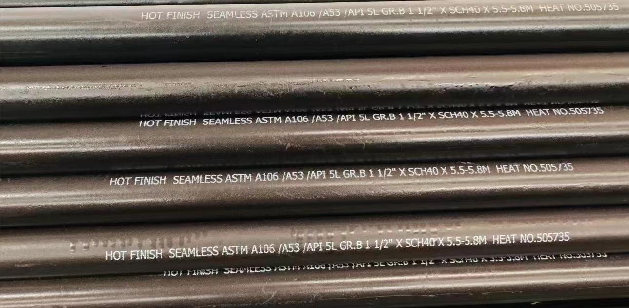
Pipe Marking and Location
Common marking elements for steel tubes:
Pipe manufacturer's name or marking ;
Marking "API Spec 5L". (Generally abbreviated to API 5L.) Products conforming to more than one compatible standard may be marked with the name of each standard.
Specified Outside Diameter
Specified wall thickness
Pipe grade (steel name)
Pipe type
Length (pipe length in m to the nearest 0.01 m (in ft to the nearest tenth of a foot))
Location of steel pipe markings
D ≤ 48.3 mm (1.900 in) steel pipe: Tabs that are continuously fabricated along the length of the steel pipe or that can be secured to the steel pipe bundle.
Pipe with D > 48.3 mm (1.900 in):
Outside surface: Beginning at a point on the outside surface of the pipe between 450 mm and 760 mm (1.5 ft and 2.5 ft) from one end of the pipe.
Inside surface: Start marking on the inside surface of the pipe at least 150 mm (6.0 in) from one end of the pipe.
Equivalence Standard
International and regional pipe and tube standards for which API 5L is the equivalent or, in certain circumstances, an alternative option, as well as a number of application-specific standards:
International and regional standards
1. ISO 3183 - A global pipeline standard for the oil and gas industry published by the International Organization for Standardization and closely related to API 5L.
2. EN 10208 - European Standard for steel pipes for the transportation of fuel gases and liquids.
3. GB/T 9711 - Chinese national standard for pipeline transportation systems in the oil and gas industry.
4. CSA Z245.1 - Canadian Standard covering line pipe for the transportation of oil and gas.
5. GOST 20295 - Russian Standard for steel line pipe for the transportation of oil and oil products.
6. IPS (Iranian Petroleum Standards) - Iranian Petroleum Standards for line pipe for the oil and gas industry.
7. JIS G3454, G3455, G3456 - Japanese Industrial Standards for transmission pipes of different pressure classes.
8. DIN EN ISO 3183 - German Industrial Standard based on ISO 3183 for line pipe.
9. AS 2885 - Australian Standard for line pipe systems for the transportation of oil and gas.
Application Specific Standards
1. API 5CT - American Petroleum Institute standard for oil well casing and tubing, which, although primarily used in oil wells, is also important in the oil and gas industry.
2. ASTM A106 - American Society for Testing and Materials standard for seamless and welded carbon steel pipe for high-temperature service.
3. ASTM A53 - National Institute for Testing and Materials standard for seamless and welded carbon steel pipe, typically used for fluid transportation at room temperature or lower temperatures.
4. ISO 3834 - International Organization for Standardization standard for quality requirements, focusing on quality assurance systems for welded metals.
5. dnv-os-f101 - Norwegian classification society standard for submarine piping systems for offshore oil and gas transmission pipelines.
6. MSS SP-75 - Manufacturers Standards Society standard focusing on high strength, large diameter circular welded steel pipe fittings.
Quality Management and Environmental Suitability Standards
1. NACE MR0175/ISO 15156 - Requirements for materials used in oil and gas extraction in sulfur-containing hydrocarbon environments, which, while primarily concerned with material selection, are important for ensuring the corrosion resistance of materials used in the oil and gas industry.
Our Related Products
API 5L PSL1&PSL2 GR.B Longitudinal Submerged-arc Welded Pipe
API 5L GR.B X60 X65 X70 PSL1/PSL 2 LSAW Carbon Steel Pipe
API 5L GR.B Heavy Wall Thickness Seamless Steel Pipe for Mechanical Processing
API 5L Gr.X52N PSL 2 Seamless Steel Pipe ACC.To IPS-M-PI-190(3) & NACE MR-01-75 for sour service
API 5L X42-X80/ API 5L X52 / PSL1&PSL2 Oil and Gas Carbon Seamless Steel Pipe
API 5L GR.B Seamless Line Pipe for Pressure and Structure
API 5L/ASTM A106/ASTM A53 Gr.B Seamless Carbon Steel Pipe
BotopSteel is a China Professional Welded Carbon Steel Pipes Manufacturer& Suppliers Over 16 Years with 8000+ Tons of Seamless Linepipe in Stock Each Month. We're ready to reply to you within 24 several hours soon after receipt of one request and also to develop mutual un-limited advantages and organization around potential.
tags: API 56 46th, Dimensional Deviations, PSL1, PSL2, suppliers, manufacturers, factories, stockists, companies, wholesale, buy, price, quotation, bulk, for sale, cost.
Post time: Mar-22-2024